
From Haphazard to Harmonized: BPT Repairs Redefines Façade Aesthetics.
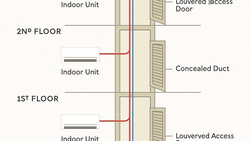
“Exposed AC copper pipes, drain lines, and electrical conduits running across the façade not only look messy but also damage the building’s overall aesthetic. The random, haphazard routing creates a cluttered appearance, reduces property value, and gives even a new building an unplanned, unfinished look. Concealing them in a well-designed duct system brings back symmetry, elegance, and professionalism to the structure.”Step-by-Step Approach
1. Centralized Vertical Duct Planning
- A vertical shaft/duct (usually 600 mm × 600 mm or as per requirement) is planned in one corner of the building façade or inside a service core.
- This duct runs from ground to terrace, serving as a common route for all AC pipes.
- Access doors (metal or UPVC louvered) are provided at each floor for maintenance.
2. Pipe Routing per Floor
- Each apartment’s refrigerant copper pipe pairs (supply & return) and drain pipes are routed horizontally from the indoor units to the nearest duct location.
- They enter the duct through sleeves with firestop sealants to ensure safety.
3. Insulation & Cladding
- Copper pipes are insulated with closed-cell elastomeric insulation (like Armaflex) to avoid sweating.
- All drain pipes are PVC/CPVC, sloped properly to the duct’s vertical drain line.
- Bundle the pipes in trays or brackets inside the duct to maintain neatness.
4. Main Vertical Lines
- From the duct, main vertical refrigerant and drain risers are carried floor to floor.
- Drain lines from each floor are connected into one vertical soil/drain stack (with proper slope and venting).
5. Duct Enclosure for Aesthetics
- From the outside, the duct is finished with aluminum composite panel (ACP) cladding, concrete shaft wall, or architectural louver panels.
- This gives the building a uniform clean façade with no visible hanging pipes.
6. Access & Maintenance
- Provide accessible doors (lockable) at each floor landing or balcony to allow pipe maintenance.
- Ensure that condensate drains have proper traps and easy cleaning access.
✅ Aesthetic appeal – No messy exposed pipes on the façade. ✅ Easy maintenance – All services routed in one duct. ✅ Long-term durability – Proper insulation prevents leakages & sweating. ✅ Architectural flexibility – Duct can be hidden with design elements.
Design Concept
- Central Vertical Duct (Service Shaft) One shaft (300mm × 450mm) running continuously from ground floor to terrace. Shaft walls in brick/block or cement board with access panels every floor. Concealed with paintable louvered doors in corridors for ventilation + maintenance.
- AC Copper Pipe Routing Each flat’s indoor units connect via insulated copper pipes (9.52mm + 15.88mm typical for 1.5TR units) to the common vertical duct. Pipes bundled neatly with cable trays/clamps to prevent entangling. Max vertical lift per VRF/split considered (25–30m).
- Condensate Drain Separate PVC/CPVC vertical drain stack (75mm) inside the shaft. Floor connections with 32mm branch lines from each indoor unit. Gradient maintained for smooth flow.
- Electrical & Control Wiring Run alongside copper lines within trunking/conduits inside the same shaft. Fire-stopping collars at each floor slab penetration.
- Terrace Connection All copper pipes terminate at terrace to connect with outdoor units (either grouped VRF systems or multiple split outdoor units). Outdoor units placed on MS angle platform with anti-vibration pads.
Dr Balaji Singh
BPT group